
In case anyone is super free and wants to read my ramblings about my build process, I’ve decided to document it here.
This is the technical post filled with boring jargon and ramblings. Head over here for the non technical post, or check out the website at https://lifeclo.cc
Back in uni, I took a module that gave me the opportunity to poke around on breadboards and logic gates. For most software developers, that would be the first and last time they have to deal with logic gates, and might not find it terribly useful. It did help me figure out how to make bitwise adders in Minecraft though, so that was sort of cool. It didn’t end there, I’ve been tinkering with Arduino and various small hardware projects since. But I never really had a good thing to build. But that changed in 2017, when I got the inspiration for lifeclocc.
The idea came to me when I saw an article about a failed kickstarter campaign. (Oh hey, they’re Singaporean too!) You can read more about my overall process over at the non technical blog. That failure made me wonder, how hard can it be to design a controller for a bunch of 7 segment displays? And that led me down this research rabbit hole.
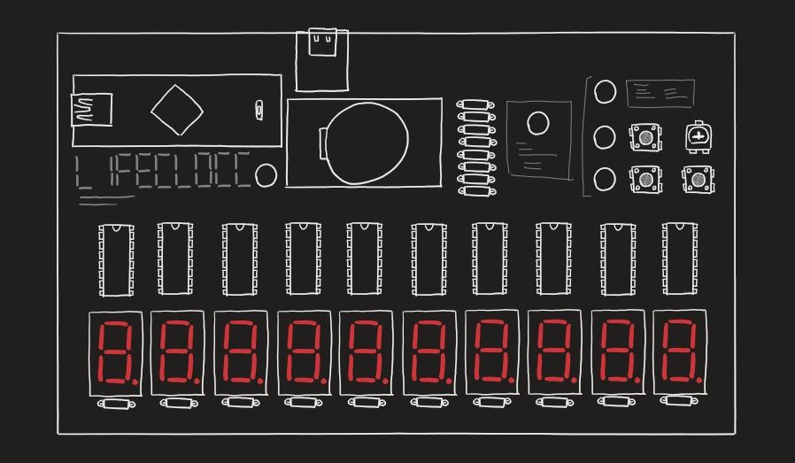
The first thing I noted was that humans live for 2 x 10 ^ 10 seconds (about 80 years). That means that I would need 10 7-segment displays. A 7-segment display is basically 7 LEDs arranged in that classic digital clock number format. That means 7 pins to control, or 8 if you count the decimal place indicator. 70 pins are required to display a human’s life in seconds. An Arduino has about... 20 ish digital output pins. Last I checked, 20 ish is much less than 70.
The basic circuit
So how does one control 70 pins with less than 70 pins? If you're the kind of person that simply googled that, you would find a very simple answer. I was not that kind of person.
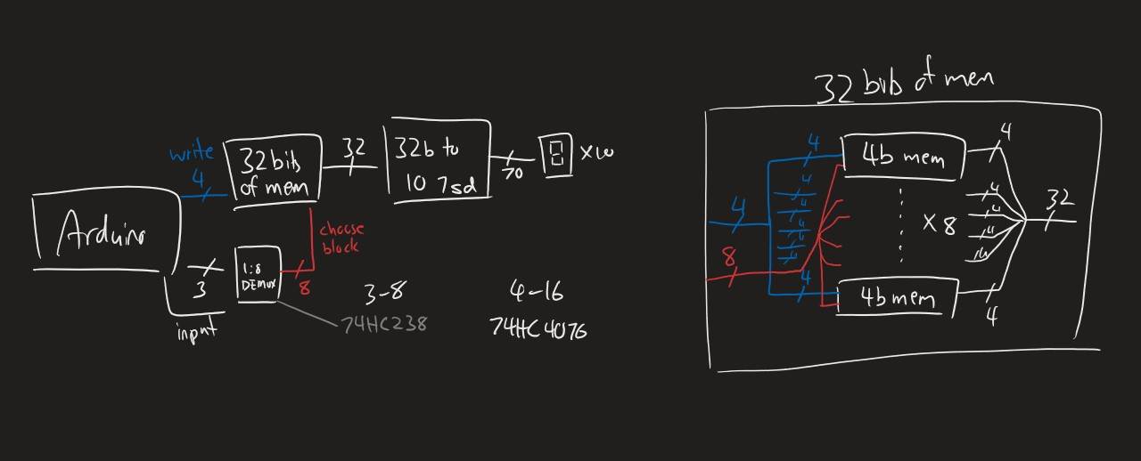
Idea 1: Multiplexers and demultiplexers
This was taken straight out of my textbook, and I started sketching a diagram on how I was going to demultiplexers to to control 70 pins. Then I realised that I would need a bunch of latches as well to hold the state if not the segments would all be flickering. I came up with a diagram that would require a lot of Demultiplexer ICs and RS Latch ICs. I never properly designed it, but it looked pretty unwieldy.
Idea 2: 7 segment decoder ICs.
I chanced upon decoder ICs while browsing Aliexpress for parts. It was essentially the demultiplexer, segment encoding and latch built into one IC. I quickly scribbled down a new circuit design and expanded on it. This is what I ended up going with for the final v1 design. It basically solved the problem of needing demultiplexers and latches for me in one convenient IC.
Idea 3: Shift Registers
<Time jump> This idea only came after I finished the v1 PCBs. In hindsight, this is the most obvious solution. If you ask any hardware engineer how to control multiple pins with limited outputs, you’ll immediately be told to use serial data. Well, I'm not a hardware engineer and had no experience with using serial data. Also the idea of dealing with serial scared me and I did not know what shift registers were or did. Now I do. With that, Lifeclocc v2 is built with these giving me way more control over what I can display on the screen.
Controlling the device
At the time of writing of this post, I have a lot more knowledge of how microcontrollers work. Looking back at the decisions made three years back is painful. But that's how you learn right?
I wanted to control the device with an Arduino Micro or Arduino Nano. This would keep the overall size of the clock small. It's also much easier to mount an Arduino Nano on a product than an Arduino Uno. I knew it was possible to use the Arduino's microcontroller directly, but at the time I had no idea how to program a standalone microcontroller so something like the Nano was my best bet.
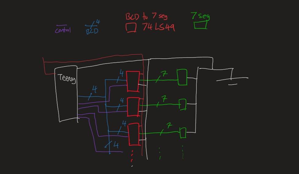
After that, I realised that the nano still didn't nearly have enough pins to control the 10 segments despite the decoder circuits I was using. It typically has 15 IO pins. I would require 10 control wires and 4 more for the binary coded decimal (BCD) bus. This didn't leave enough pins to control things like LEDs, buttons or the clock.
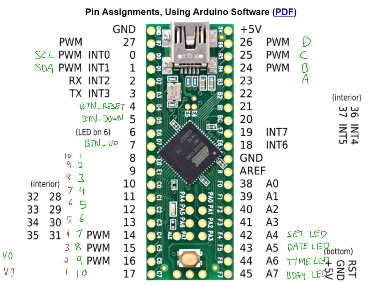
That's when I discovered the Teensy. It has roughly the same footprint as the Arduino Nano but with way more processing power and pins. It was also almost completely compatible with the Arduino software.
Building the base circuit
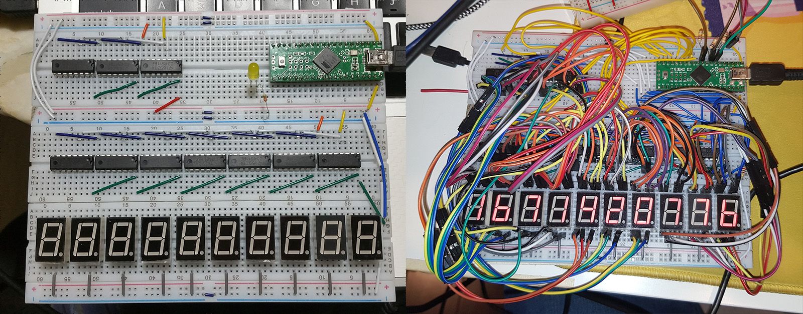
The initial circuit was quite straightforward. I put the decoder ICs on a breadboard and put the 7-segment displays below.
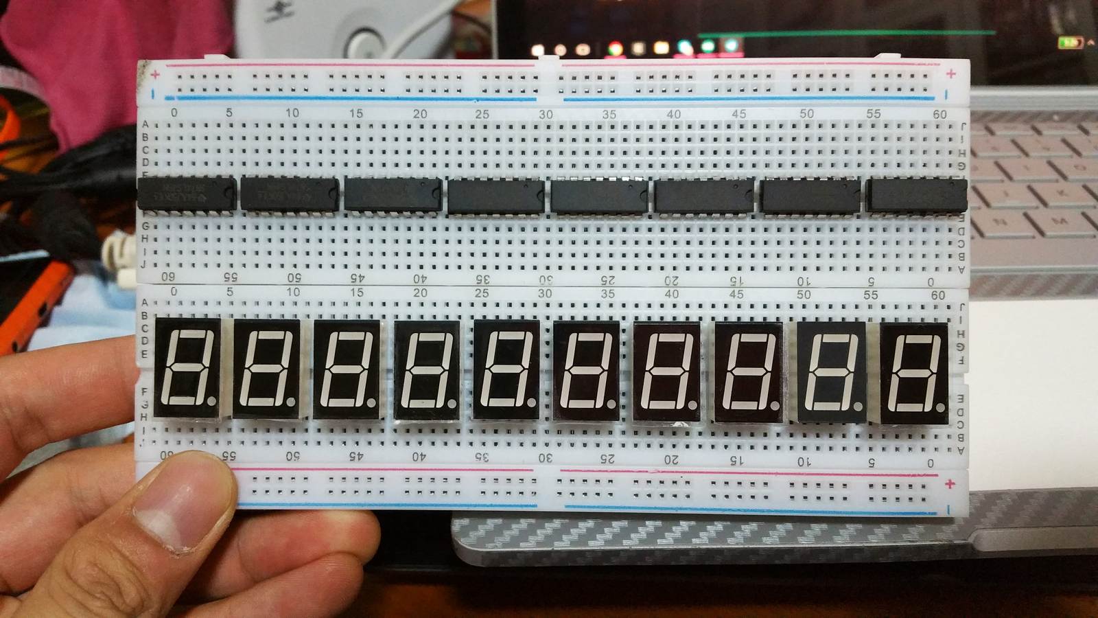
Unfortunately, the ICs were longer than the displays so I couldn't make it fit nicely on 2 breadboards, so I ended up with a mess of wires and a third breadboard.
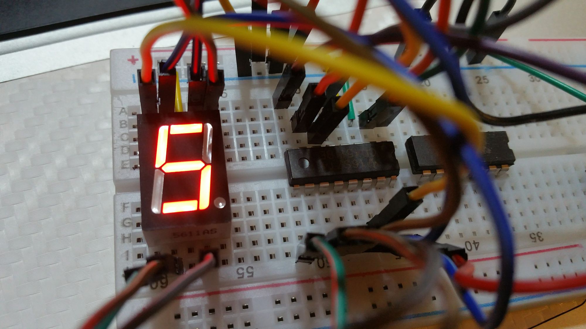
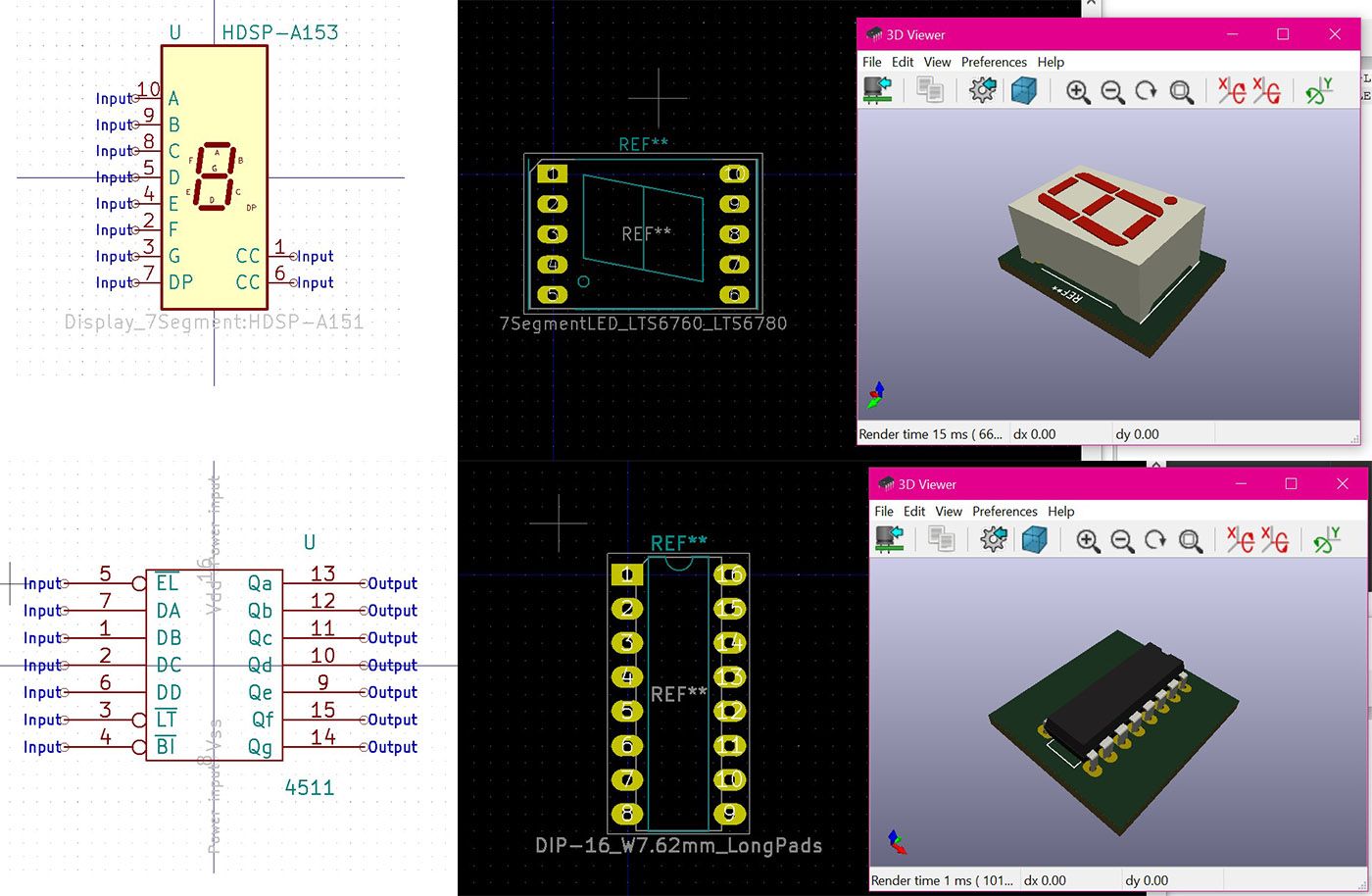
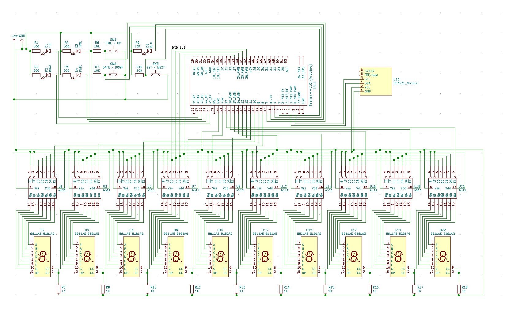
The decoder I used was the 4511. This has 5 important input pins. 4 of them would give the number in binary, and the last pin was the latch. If the latch is high, it would save the previous number that was passed in through the BCD (Binary Coded Decimal) pins. To set it, I had to set the BCD pins, turn off and on the latch, and the IC would output the segments required to display that number..
Next, it was a matter of hooking up the BCD wires to the right pins and connecting the latch control wires.
Initial code
The original code was lost to time since I was terrible at backing up anything, but it was easy enough to recreate. I took 80, subtract my age and got 55. Then I simply multiplied the number by the number of seconds in a year, with the result being 1735668000.
Then it was a matter of writing a function to convert the number into something that could be displayed, setting the number on the BCD bus and sequentially setting each digit. This happened fast enough that it would appear to all change at the same time. Using the built in clock, I subtracted the number once every second.
I won't get into any more detail about how I did that. You can check the code out on github.
At this point, I had a glorified working countdown timer and it was good enough. It was working* with a lot of caveats.
* Users could not control it without access to a computer and the code.
* Everytime it loses power, it will lose its memory as well.
* It always starts from the same number when you restart it.
* Time probably would drift since it didn't have a proper clock in it.
I left it in this state for 2 years.
Keeping Time and Data Across Restarts
Just as quickly as I had stopped, I got the motivation to finish up the product. I was most excited to create a PCB for lifeclocc, but it needed to work as a proper clock first. And the most basic thing is to be able to continue keeping the time even if it gets unplugged.
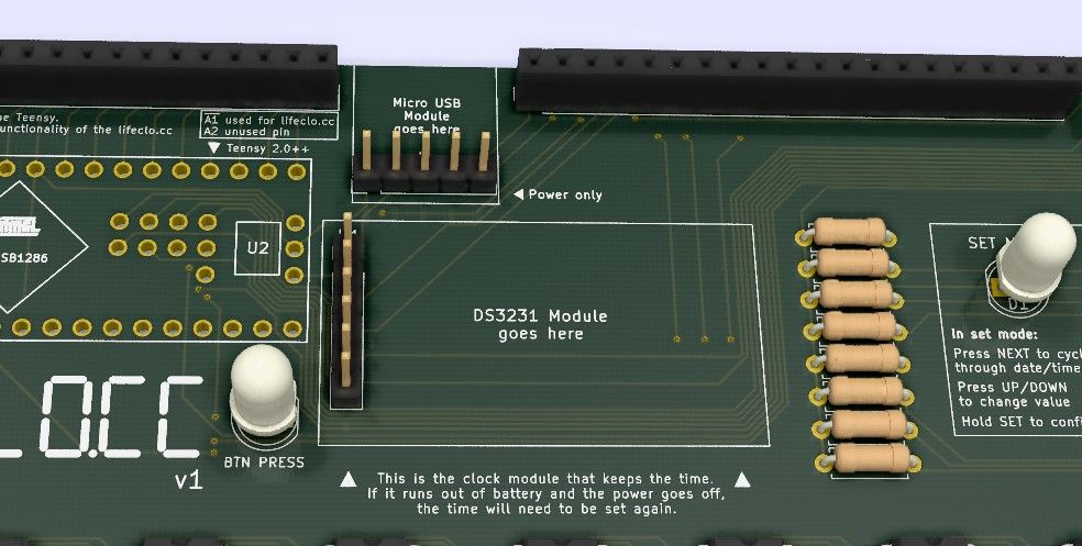
This was a fairly simple task to implement. I searched for a Real Time Clock (RTC) module and read what the internet thought about it. The DS3231 appeared to be the most recommended because of reasons like quartz clock. That sounded good to me. I like crystals in my machine.
The next part was following a bunch of tutorials and reading documentation. This was fairly straightforward to implement given the vast variety of resources available. With that, I had a device that could keep its time even if the power went out.
Next I started looking into saving the user's birthday across restarts. I played around with adding an SD card to lifeclocc so that I could save data when the clock lost power. SD cards would add to the cost of the clock and it felt a bit overkill for my needs, but I didn’t know any other way to save data. I was almost resigned to needing to use SD cards on my clock, when I discovered the magic of EEPROM.
EEPROM is a small bit of memory (typically 1kb) that comes on the Arduino and Teensy that allows you to store small amounts of data, akin to a hard drive. In my defence, I was trying to integrate SD cards because I happened to have an SD card reader on hand. I had also worked with SD cards on an Arduino before.
After all that, saving the birthday was as simple as writing some code. No additional hardware or wiring involved.
Sidetrack: The lifeclo.cc website
Making websites is what I do for my day job, so I managed to get it up and running fairly quickly That’s not the important bit. The important part here is the name, lifeclocc.
Some people have asked why it’s called lifeclocc and not deathclocc. Firstly, I like to maintain a positive spin to the product, and I don’t want it to be constantly reminding the user of their death. It’s meant to focus on the life left and all the things you can do with it.
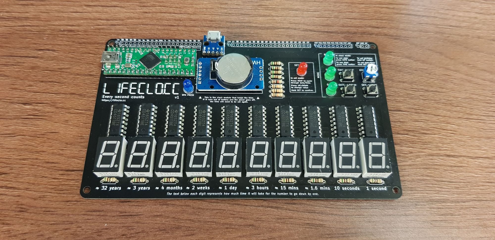
But on a more practical note, the letters LIFECLO.CC can be perfectly spelt out on a 7 segment display. That made me really happy, also the domain was available which was great as well.

Considering User Inputs
Now that I had the clock, I needed a way for the user to change the time. Programming the time from a computer was working for me, but any product would need to have user controls if we wanted it to be a usable standalone product.
There are many ways to control a device, but push buttons are the easiest to implement. I'm not a UX designer by any means, but I have had plenty of experience setting desk clocks and digital watches before everything became touch screen enabled. I used that idea as a base and created a basic user interface around the buttons.
I also drew a state diagram because I was feeling too bored apparently.
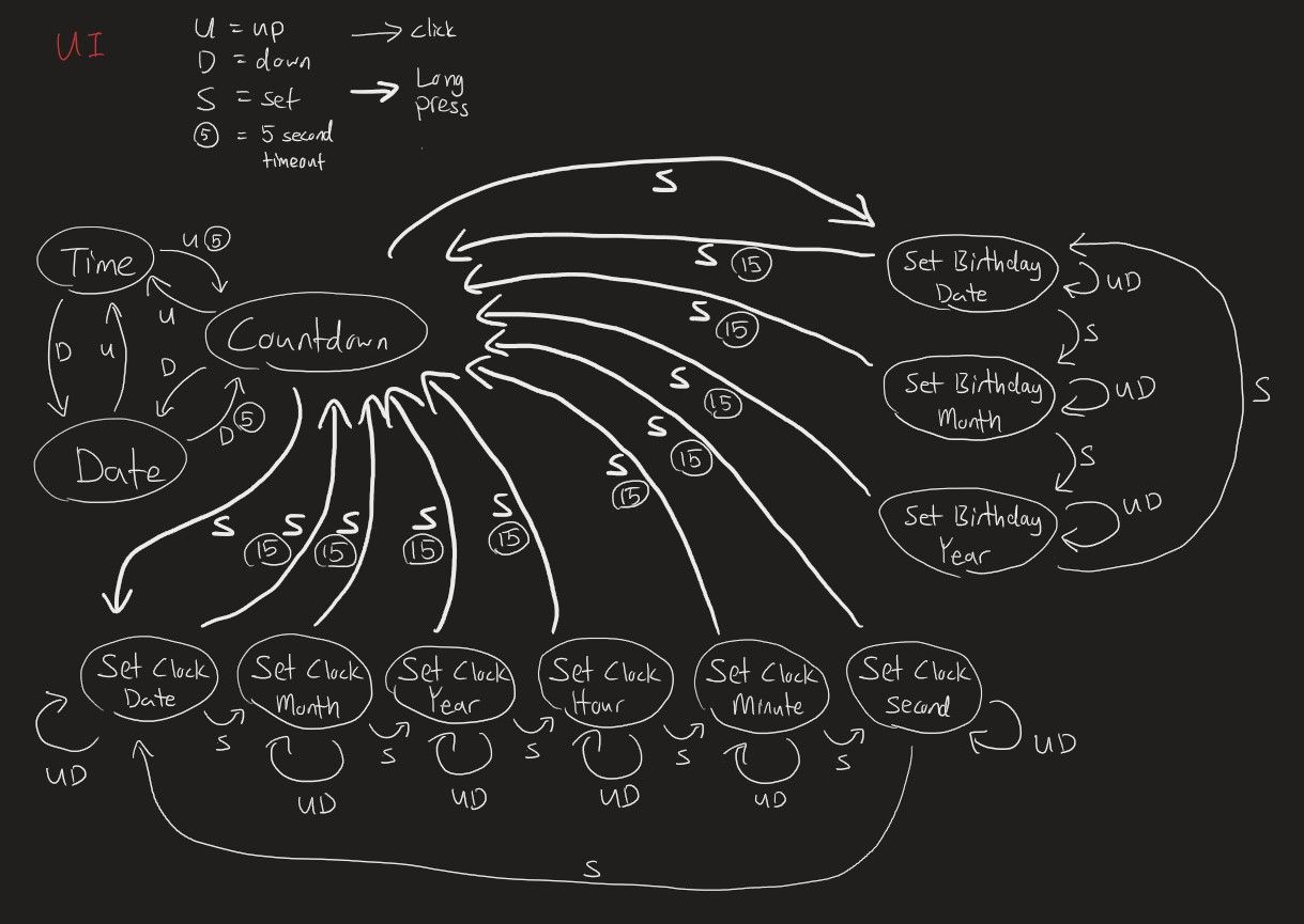
If that's not clear enough, the basic idea is to have the user press and hold the "set time" button. When it's in set mode, the user can press up and down to change the numbers. Pressing the set button again would move to the next number.
I also threw in a potentiometer to control the brightness after I realised that the clock was way too bright at night.
Making it real with PCBs
Now that I had the circuit complete, I needed to figure out how to make the PCB. I had no idea how to start designing PCBs, but I did know that Eagle and KiCad were the industry standards. I decided to go with KiCad because it is open source and all features are free. I read somewhere the Eagle limits you if you need to do some advanced stuff. Also KiCad has a 3D viewer and Eagle doesn’t appear to have one.
The first thing to do was to figure out how to even start using the interface. Clicking around did not do anything, it was not very intuitive. I find that the best way for me to learn this is to search for a short tutorial on how to create a basic PCB in KiCad. I found a 5 minute video that ran through the steps to create a basic PCB.
For each component, KiCad has two different parts that need to be designed / selected.
- The schematic, the thing that defines the pins that need to be connected. This is used in the schematic design view.
- The footprint, the one that defines the size of the layout physically and sometimes comes with a nice 3D model to visualise it. This is used in the PCB design view.
To get it working, I needed to add schematic components to the screen and link them up. Sounds straightforward enough, except there were components that I used that didn't seem to exist in the KiCad library. The Teensy component was easy, because someone had already created that component and it was just a matter of loading the library. But the DS3231 module I was using definitely had a different pinout than the DS3231 in KiCad. So I had to learn how to create custom schematic component.
Once the schematic layout was done, it was time to put the components on the PCB. That's when I ran into the next problem. There is a huge library of component footprints, but there wouldn't be a component for the breakout boards I use. As it turns out, there are generic 2.56mm header pin components, so I just needed to choose the generic pinouts for each of the components.
The only other thing I had to do was to ensure the pins were labelled correctly. I encountered a wiring error when one of the components had a different pin numbering than the one I was using. KiCad does allow you to change the pin numbering, but it's good to check.
When I was satisfied with the PCB, I put in my order. The process was super simple and only required me to upload the gerber files. The quote was provided instantly and I paid for it on the spot. I was quite amazed as to how fast and cheap getting your own PCBs were. The base cost is $5 and you pay about $20 for shipping (to USA).
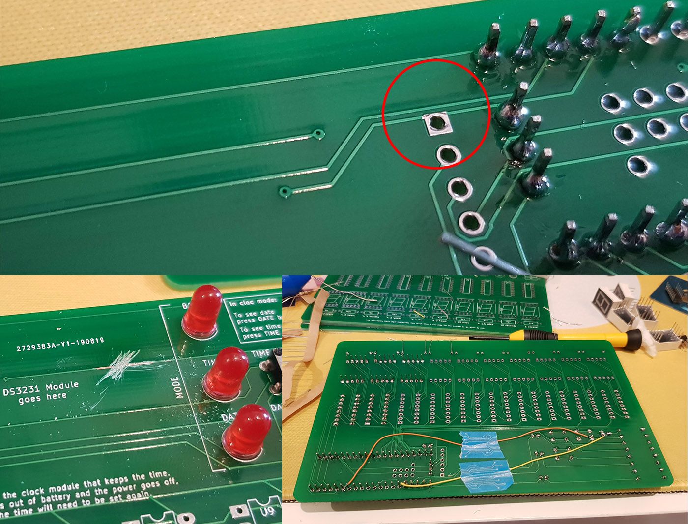
One week later I received my PCBs all excited-like and soldered it. Only to find out that I crossed some wires when designing it. That's when I also learnt (the hard way) that KiCad, or any other PCB design software for that matter, has a button that would check if any of the wires were in unexpected or illegal places.
That was unfortunate, and I'm pretty sure it broke one of the pins on the microcontroller when I plugged it in and short circuited it. Luckily the rest of the microcontroller was still working and I could fix it by taking wires and rewiring the board manually. Also I had to scratch the broken wire off the board to prevent the short circuit, but I managed to get the prototype working.
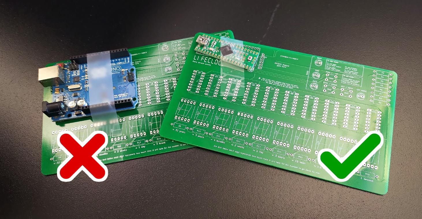
The next step of building v1 did not have any hiccups. I had learnt a lot from my experiment with v0 and I encountered no problems with this version. It was at this time that I decided that I had a *good enough* product. That’s the black one you see on the website right now.
Bonus: Here’s a gif of me doing the PCB design of v2.
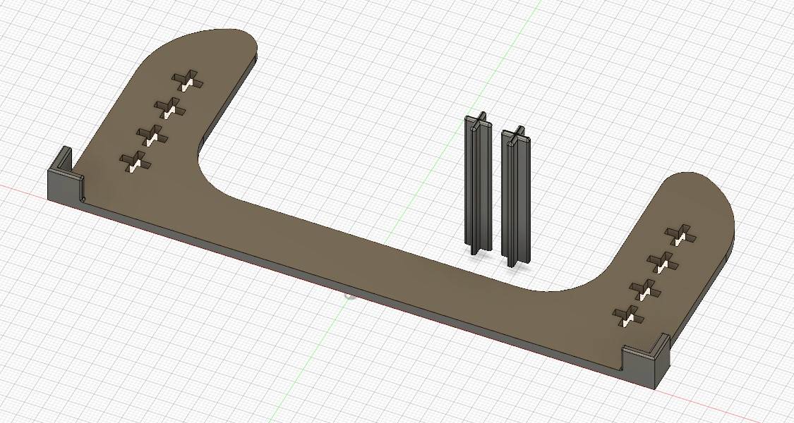
Keeping it upright
The final lifeclocc looked as awesome as I imagined. But it was missing one small thing, the ability to stand upright. Originally I considered putting a few screws through the holes I made in the corners to work as a stand. But then I decided to make use of my 3D printer conveniently lying around.
I also took this opportunity to learn another program: Fusion 360. Every 3D printing YouTube channel I see talks about it like blender isn't the most obvious program to make 3D models.
Fusion 360 was fairly straightforward to learn. Having never touched a CAD software before, I hate to have to say that it’s better to use than blender for creating models to be 3D printed. So much for my experiments with blender and 3D printing.
I made two designs, the first one did the job of keeping the clock upright. But it didn’t allow any adjustment of the angle, and there was no way I was going to be able to ship it without breaking something or adding a whole lot of padding.
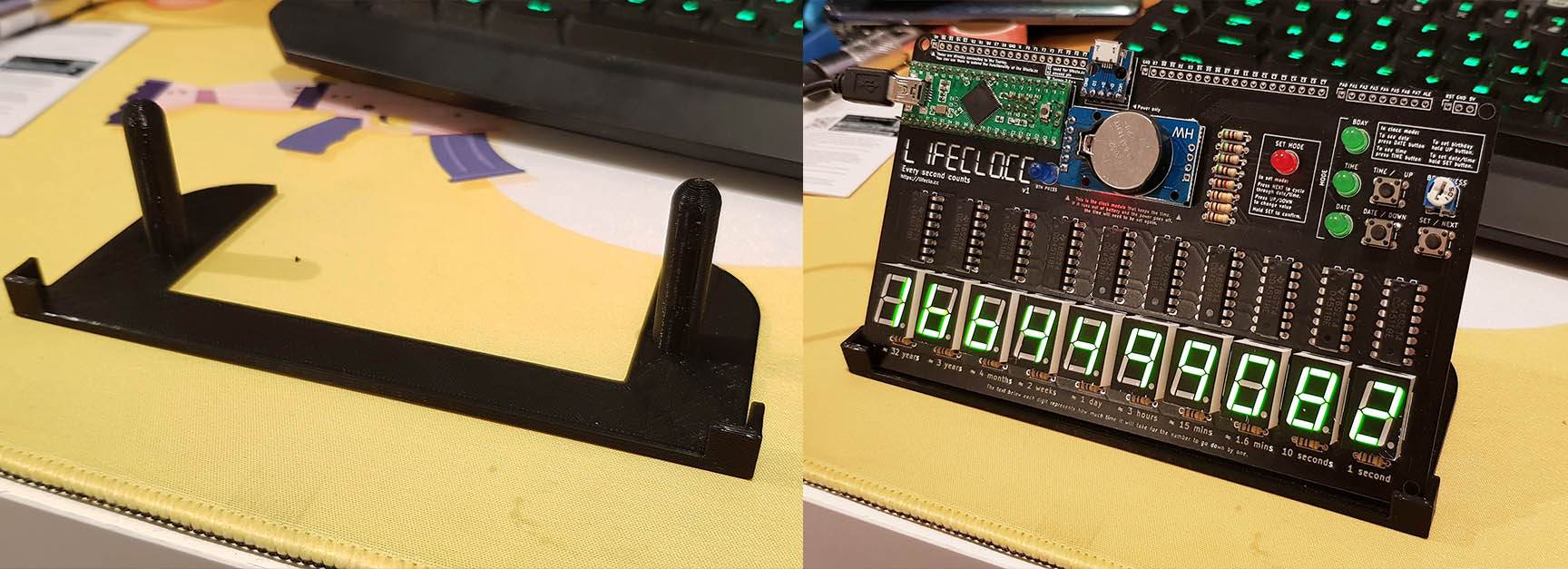
For my second design, I simply took inspiration from lego technic axles and punched a few holes into the base. This would allow it to be flat packed as well as make it adjustable.
I had originally planned to create a hinge system, but that was admittedly a lot more effort to get right. The main focus of this project was the PCBs and clock anyway.
Future iterations
Everything I put here really doesn't mean anything until I actually execute it. There are always plenty of ideas to go round but not enough time to complete them.
Since the creation of v1, much thought has been put into the product, and I've shown my idea to friends. Below is a list of features that I could potentially incorporate into the next few iterations.
Use shift registers
As mentioned above, this will allow me to individually control the segments opening up the possibility of showing characters on the display modules. As it turns out, it worked wonderfully, and I am currently working on a V2 using shift registers. V2 is controlled with an Arduino Nano, bringing the cost down and making it slightly easier to code for.
Use SMD components
Using SMD components will serve a few purposes, firstly, I'll be able to make this much smaller than it currently is. I could even make a portable one that you can wear around your neck, like a badge. The market for that would specifically be DEFCON attendees I suppose.
Add a clock display
I debated doing this when I was creating the first one, but decided against it. I wanted the first version to focus on the life running out aspect, and not the time. But I realise that it's probably more useful as a clock and if I want to actually sell this, it might do better as a desk clock than just another piece of clutter.
Add a battery
This will require me to figure out how to reduce the power usage so as to make the battery idea feasible. I think it'll need to last at least a few months on a single charge for it to be worth putting a battery in, otherwise people will likely just leave it plugged in anyway. The main issue is that the 7 segment displays take up quite a bit of power. There are low power modes on the Teensy microcontroller, and I might even be able to figure out how to run this off an ATTINY, so those aren’t the issue.
Add a light / motion sensor
Kind of in conjunction with the battery thing, having a motion sensor means I can dim the screen when there is no one around would save power.
Add wireless connectivity
Probably not. This is pretty much scope creep at this point and opens up a whole new world of bugs and potential security flaws to deal with.
Add a (manual) activity tracking function
Someone mentioned that if I added a button to allow you to "clock in" and "clock out" of work, you'll know how much time you spend at work. It could also be used to track other things like habits you want to form. It sounds like a cool idea, but the implementation also sounds like a pain. I almost feel like It’ll need an app at that point. I don’t have the time for that and I’m already busy coding another app anyway.
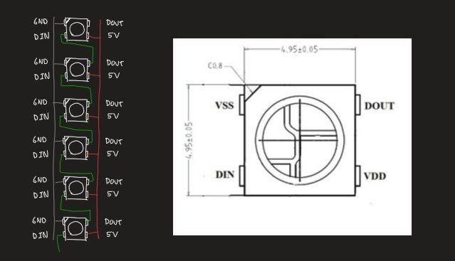
Use bar graphs and other flashy lights
As a matter of fact, I’ve been playing around with individually addressable pixels. Though I have no idea what I want to do with that right now.
In conclusion
I don’t really have anything to conclude, but the post felt a bit abrupt without an ending.
This took me over 3 years to develop. Throughout that time, I learnt a lot about making stuff, personal time management and prioritising my vast array of interests. I will continue to obsess over new and interesting things that catch my fancy. I hope that I do end up figuring out the marketing aspect of this and putting this on sale for people to have before I commit myself to my next project.